Following are the interactive versions of the circuits used in the document:
Arithmetic circuits are used to perform several different arithmetic operations using a single composite circuit. Half adder, subtractors etc., are examples of arithmetic circuits.
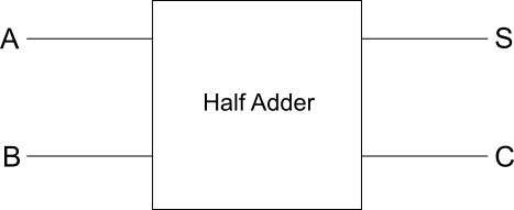
Half Adder
Half adder is an arithmetic circuit that performs arithmetic addition of two binary digits. Following is the details of a half adder.
Block diagram
Truth table
| A | B | S | C |
|---|---|---|---|
| 0 | 0 | 0 | 0 |
| 0 | 1 | 1 | 0 |
| 1 | 0 | 1 | 0 |
| 1 | 1 | 0 | 1 |
Circuit diagram
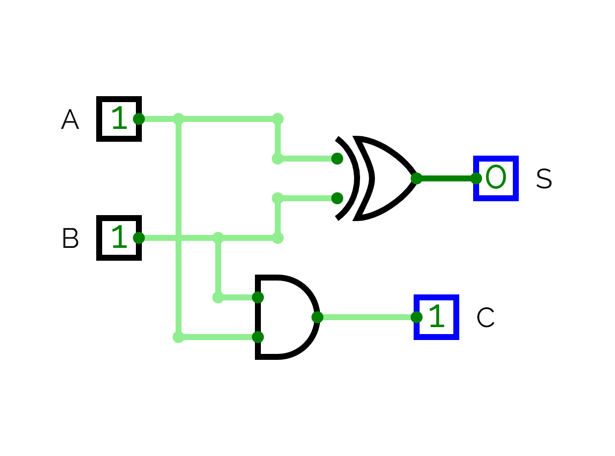
Working
-
It has two inputs and , and two outputs sum , and carry .
-
The sum is derived with
XORoperation on the inputs: -
The carry is generated by
ANDoperation on the inputs:
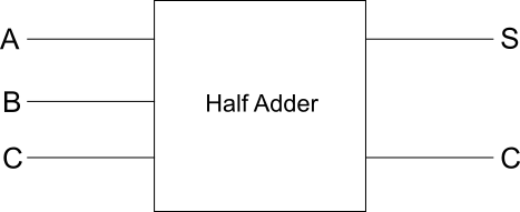
Full Adder
A full adder is a combinational circuit that performs arithmetic sum of three input bits, and produces a sum and carry .
Block diagram
Truth table
| A | B | C | S | C |
|---|---|---|---|---|
| 0 | 0 | 0 | 0 | 0 |
| 0 | 0 | 1 | 1 | 0 |
| 0 | 1 | 0 | 1 | 0 |
| 0 | 1 | 1 | 0 | 1 |
| 1 | 0 | 0 | 1 | 0 |
| 1 | 0 | 1 | 0 | 1 |
| 1 | 1 | 0 | 0 | 1 |
| 1 | 1 | 1 | 1 | 1 |
Circuit diagram
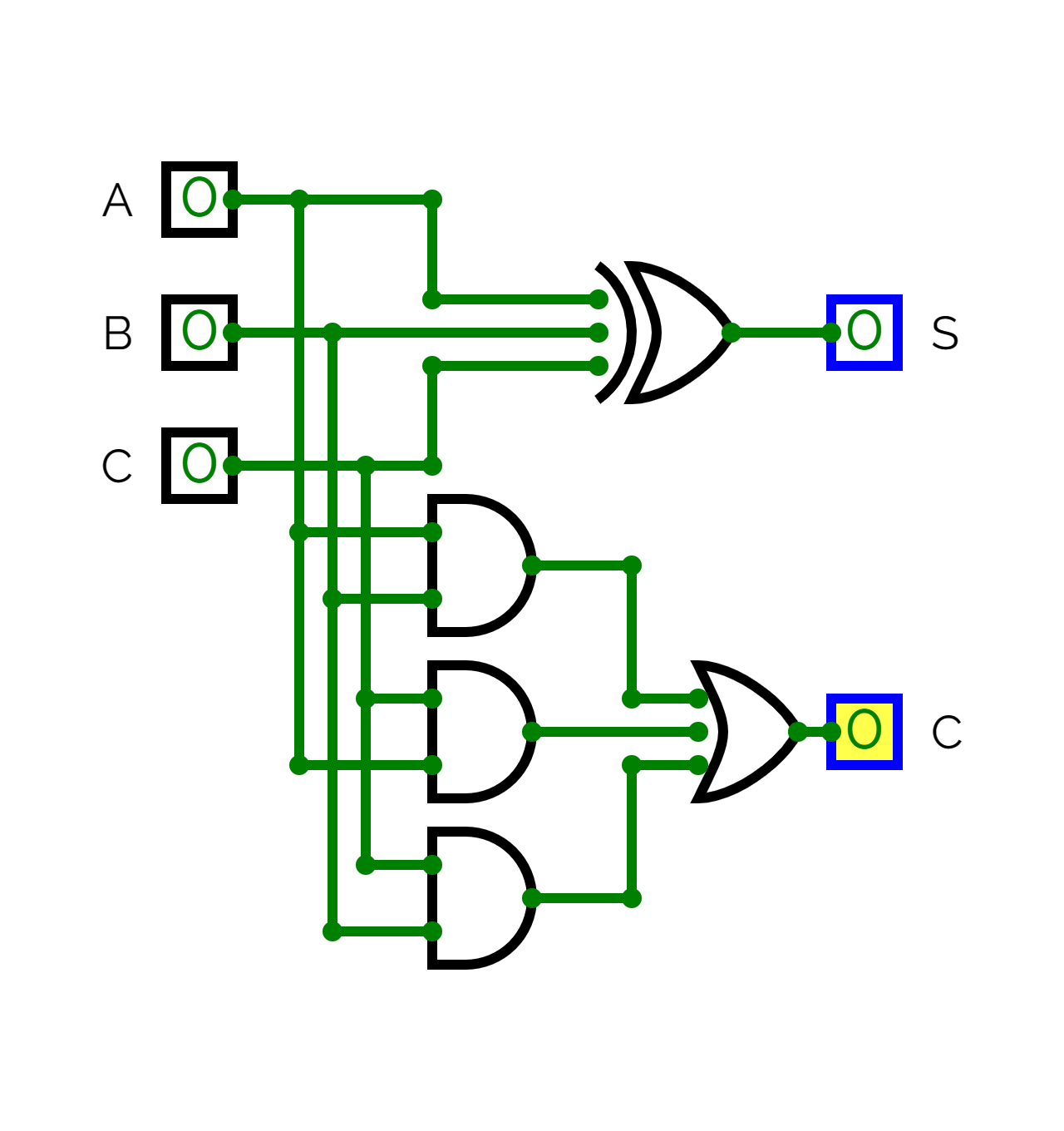
Working
-
It consists of three inputs denoted by (augend bit), and (addend bit), and third input , which represents the carry from the previous lower significant bit.
-
It produces two outputs sum , and carry .
-
From the above truth table using S.O.P. (sum of products), the formula of sum is derived as follows:
- From the above truth table using S.O.P. the formula of carry is:
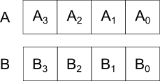
4-bit Parallel Adder
This circuit is capable of adding two 4-bit binary numbers resulting in four bit sum and a carry.
Construction
Binary bits:
Design:
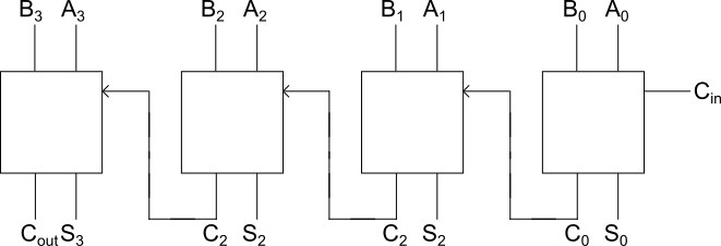
- Two 4-bit binary numbers are in storage and .
- Four full adders are used.
- The input is always 0.
- and and carry from the significant bit is fed as input to produce sum and the carry generated is forwarded to the next full adder.
- is the final carry
Working
- In least significant bit, , , and (which is 0) are added to produce sum and carry .
- Similarly all the other inputs are added in respective full adders.
- If no carry is generated 0 is forwarded.
- In case a fifth bit is generated in the final sum it is produced through .
4-bit Combined Paraller Adder/Subtractor
The 4-bit parallel adder/subtractor circuit is capable of performing both addition and subtraction on two binary numbers.
Construction
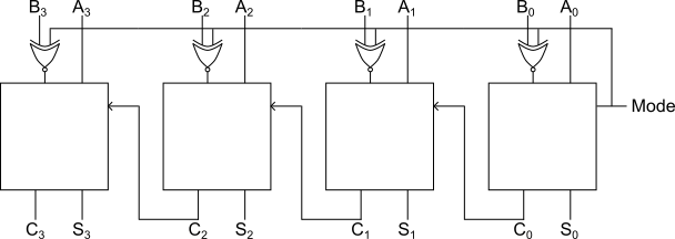
- Two 4-bit numbers are stored in storage and .
- bits are fed into the full adders directly.
- The inputs are fed via
XORgates. - The other input of
XORgate are kept common and connected to the input of first full adder known as mode.
Working
When mode is 0, we can understand the working if we concentrate on the first full adder, the inputs are:
Therefore, the circuit acts as an adder circuit.
But when mode is 1, the inputs are:
Therefore, the circuit acts as a subtractor.
Half Subtractor
A half subtractor is an arithmatic circuit used to subtract two binary digits. It takes in two inputs and , and returns two outputs: difference (), and borrow ().
Block diagram
Truth table
| 0 | 0 | 0 | 0 |
| 0 | 1 | 1 | 1 |
| 1 | 0 | 1 | 0 |
| 1 | 1 | 0 | 0 |
Circuit diagram
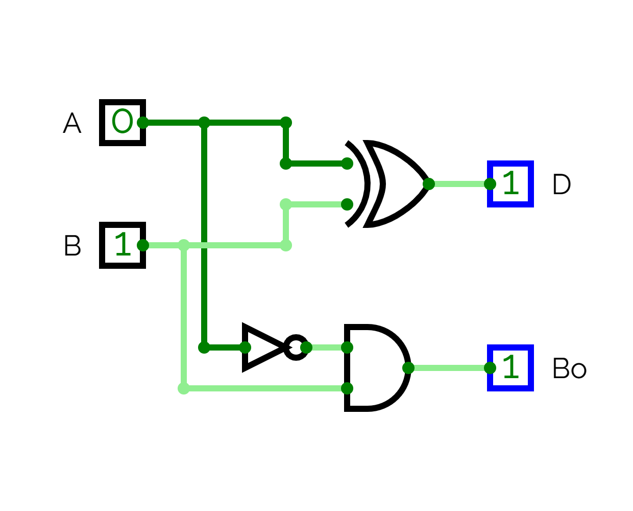
Construction
- Two inputs and are passed directly into the
XORgate which gives the difference . - The inputs from is first passed into the
NOTgate then along with is passed into theANDgate giving the borrow .
Working
-
The formula for the difference can be brought out using the truth table:
The above is a formula of a
XORgate. -
The formula for borrow can be brought out using truth table as:
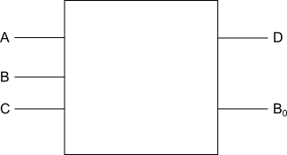
Full Subtractor
A full subtractor accepts three input lines of binary digits and returns their difference and respective borrows.
Block diagram
Truth table
| 0 | 0 | 0 | 0 | 0 |
| 0 | 0 | 1 | 1 | 1 |
| 0 | 1 | 0 | 1 | 1 |
| 0 | 1 | 1 | 0 | 1 |
| 1 | 0 | 0 | 1 | 0 |
| 1 | 0 | 1 | 0 | 0 |
| 1 | 1 | 0 | 0 | 0 |
| 1 | 1 | 1 | 1 | 1 |
Circuit diagram
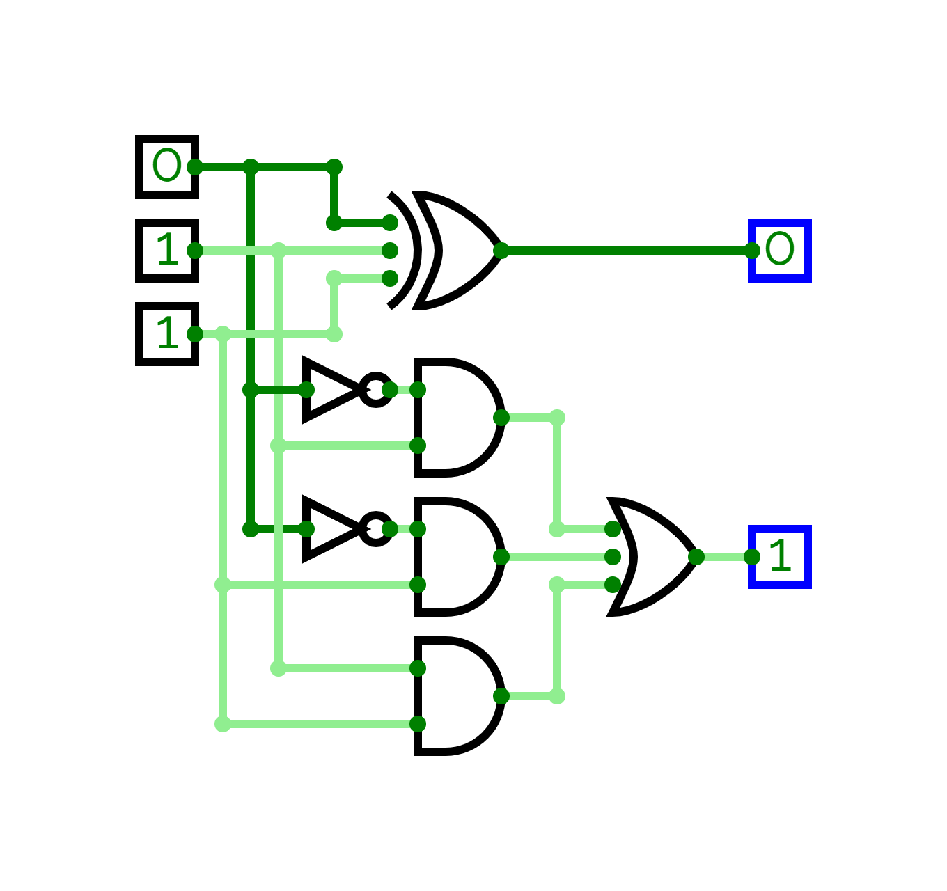
Construction
- There are three input lines, which are passed directly into the
XORgate, which gives us the difference . - And two consequetive lines from three input with each combination with a
NOTgate through , and noral lines through others are passed into respectiveANDgates to form, , , and combinations. - Finally the three combinations are passed into an
ORgate to get the final borrow
Working
-
Using S.O.P., we can find the formula for difference from the truth table as:
Therefore, the result is that of a
XORgate -
Using K-map, the formula for borrow can be brought out as:
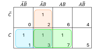
From the blue region, we have as common, from yellow region, we have as common, and from the green region we have, common.